XBee Kill-a-Watt Transmitter
06 Oct 2013
For a few months I have had the parts to build another transmitter for my XBee / Kill-a-Watt power measuring system. Since I’ve already chronicled the overall system but didn’t have any photos of the process, this post will provide the pretty pictures I lacked before.
The Parts
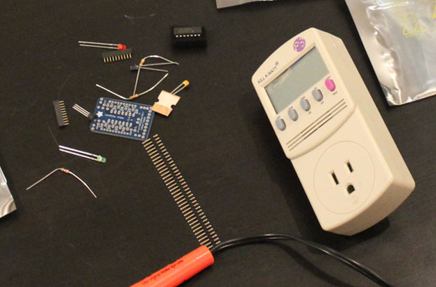
I started with parts from Digi-Key and Adafruit. At the outset, you don’t start with much.
All the parts aren’t pictured above, but here’s the full parts list (save a few resistors, heat shrink and ribbon cable):
- Adafruit XBee Adapter Kit
- XBee Series 1 with U.FL connector
- 2.4 GHz RF Antenna
- P3 Kill-a-Watt
- 50V, 1A Diode
- 220UF 6.3V Capacitor
- 10000UF, 6.3V Capacitor
- Green LED
It would have been easier to purchase the add-on kit from Adafruit, but I had enough parts lying around and wanted to get the XBee module with the U.FL connector to as receiver XBee. After the initial build I found that the XBee Series 1 that ship with the Adafruit kits could barely communicate between adjacent rooms.
The Easy Part
There are several small parts and headers you solder onto the XBee adapter board before you start doing more hacky stuff. Here’s a picture at about that point.
You can see how short those 10-pin headers are from the first picture. Getting these parts to fit under that height is easy, but the next parts, no so much.
Finishing the Transmitter
The next several steps are kinda messy. You need to solder second resistors onto two already on the board and the 220uf capacitor gets bent underneath where the XBee module will sit. The leads coming from those resistors get soldered onto the leads from the 10000UF capacitor. The diode gets added to the positive terminal of the capacitor and everything gets covered in heat shrink.
Instead of separated ribbon cable I used solid wire. If I make another transmitter, I would use braided wire (or separated ribbon cable) due to it’s flexibility.
Integrating into the Kill-a-Watt
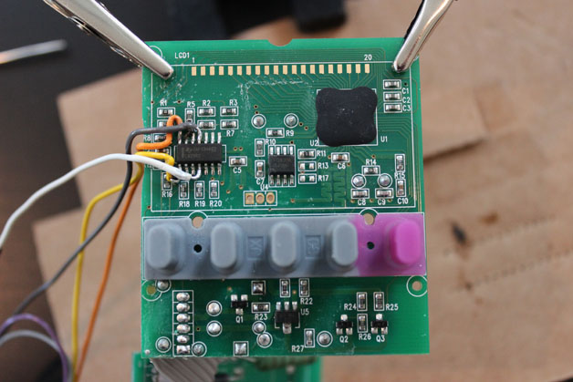
The next step is to open up the Kill-a-Watt and figure out whether you have a P4400 or a P4400.1. The later has a smaller version of the 2902 op-amp which is located behind the Kill-a-Watt display. The leads for the display can be seen in a line between the two clips in the photo below. the display must be flush against these for the Kill-a-Watt display to function correctly, and with the tight fit, getting the leads from the op-amp around the board to the backside of the Kill-a-Watt housing can be a challenge. It’s difficult to see in the picture below, but I shaved a millimeter or so off the left side of the PCB. The “R” in R8 is partly shaven off.
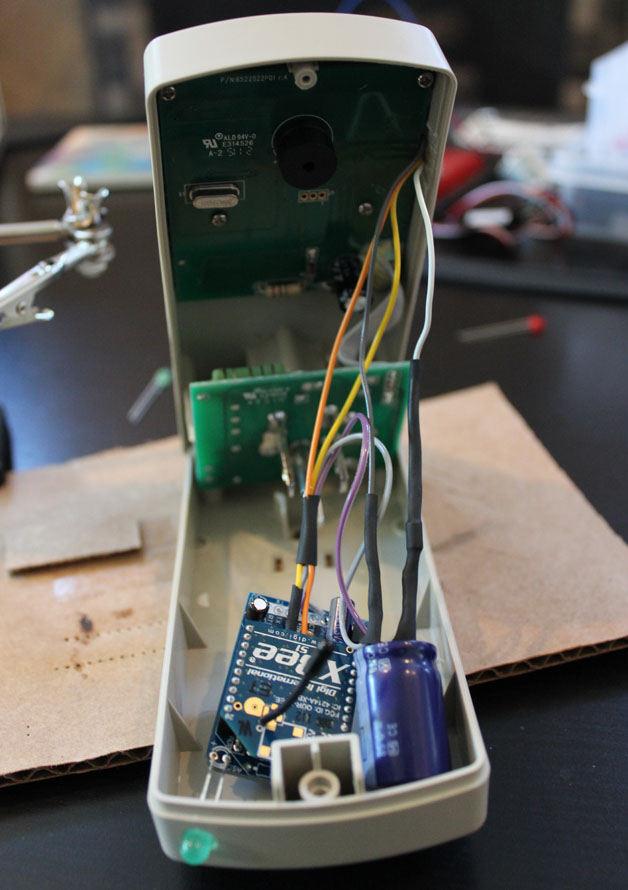
I also used a razor blade and chisel to whittle away some of the inside of the plastic Kill-a-Watt housing. It’s difficult to see, but absolutely essential to being able to re-seat the PCB in a way that allows the display leads to connect correctly. There are two supporting plastic pieces in the middle of the right side of the PCB, which is the best spot to whittle the plastic. Additionally, I recommend using something like 3M Command Hook backing tape to adhere the XBee and capacitor to the housing so they don’t rattle around.
I would recommend testing before you seal up the unit. Also, don’t forget to program the XBee to have a different ID than any other transmitters you may have.
All Done!
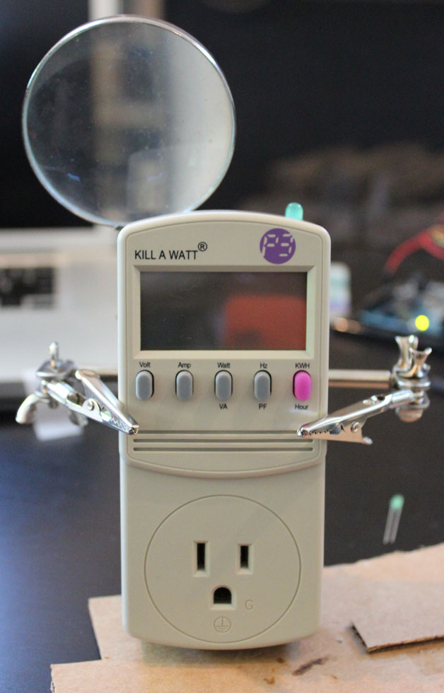
The third-hand tool gives the transmitter one last hug before the transmitter goes into service.


